Faculty
Department Faculty
Our faculty are renowned leaders in their respective fields, extraordinary teachers, and dedicated mentors.
Home to world-class teaching and interdisciplinary research, the Department of Electrical and Computer Engineering prides itself on immersive education, creative problem-solving, and close mentorship, with emphasis on devices, system engineering, signal processing and machine learning.
Vanderbilt researchers have developed a way to more quickly, and precisely, trap nanoscale objects such as potentially cancerous extracellular vesicles using a cutting-edge plasmonic nanotweezer.
 A shared passion for research and education is a hallmark of the Vanderbilt environment, and our undergraduate and graduate programs exemplify that drive for excellence. Faculty, research engineers and students engage in leading scholarship and significant research in both industry and government.
Electrical and computer engineering graduate students pursuing M.S. and Ph.D. degrees work with our accomplished faculty on high-impact research projects while gaining experience in specialized areas of interest. Focus areas include carbon, diamond and silicon nanotechnology, hybrid and embedded systems, medical image processing, photonics, radiation effects and reliability and robotics.
We offer an ABET-accredited electrical and computer engineering undergraduate degree and a double major in electrical & computer engineering and biomedical engineering, as well as several minors.
The immersive Senior Design Project brings together interdisciplinary teams of engineers to solve cutting-edge problems. Prior teams have gone on to start companies, lead to new industry products, and kickstart research careers. Summer research opportunities are also available in collaboration with the School of Engineering and the NSF Research Experience for Undergraduates (REU) programs.
s we all close the longest daylight of the year and enjoy the last few later sunsets , our ECE department has been largely looking outward. In 3 weeks, we will host scientists from 33 countries at the Medical Imaging with Deep Learning Conference (including, Australia, Austria, Belgium, …). With the support of Vanderbilt’s sesquicentennial, we are highlighting Vanderbilt beautiful campus with the assistance of the Student Life Center while branching into the community with events in partnership with the National Museum of African American Music and Parthenon. Focusing on our regional community, we are Scaling Success with the support of the Office of the Vice Provost for Research (OVPR) to build a Mid-TN AI for Interdisciplinary Imaging Interpretation Alliance (AI4A). Over the next 6 months, we look forward to deepening partnership in AI with Fisk, TSU, and TennTech.
 Prof. Yuankai Huo ’s collaborated with a broad consortium to study fatty liver diease for this week’s research highlight. (Torgersen et al., 2023) Their deep characterized the performance of Dr. Huo’ deep learning algorithm (automatic liver attenuation region-of-interest-based measurement [ALARM]) to identify steatosis within clinically obtained non-contrast abdominal CT images. His method compared favorably with manual radiologist review.
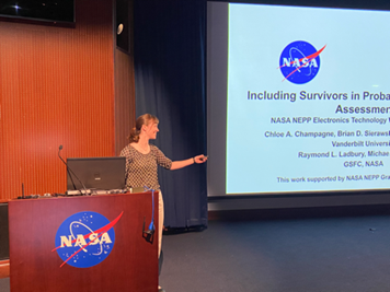
Chloe Champagne (graduate student, below) presented her research “Including Survivors in Probabilistic TID Failure Assessment” at NASA Goddard’s Electronics Technology Workshop.
Kellen Arnold(graduate student) is working with a National Science Foundation Industry-University Cooperative Research Centers (NSF IUCRC) to present “Harsh Environment Testing, Validation and Understanding of Silicon Photonics.” Prof. Art Witulski presented “Development of SEB-Immune High Voltage SiC Power Devices for Lunar Applications.”
Our research-in-review continues with the theme of advancing in understanding electronic devices. Zixiang Guo led an international team with Profs. Enxia Zhang, Robert Reed, Ronald Schrimpf, and Daniel Fleetwood along with Interuniversity Microelectronics Centre (IMEC, Belgium).(Guo et al., 2023) There efforts studies total-ionizing-dose (TID) effects in back-gated IGZO thin-film transistors.
The Biomedical Image Analysis for Image Guided Interventions Laboratory (BAGL) (led by Prof. Jack Noble) had a banner week in publishing. Katelyn Berg led a multi-university/industry collaboration in cochlear implants with Prof. Noble characterizing the effects of the number of channels and stimulation rate on speech recognition and around quality.(Berg et al., 2023) Rueben Banalagay and Prof. Noble developed an image processing technique using deep learning to identify the chorda tympani.(Banalagay & Noble, 2023) Hannah Mason and Prof. Noble combined traditional image processing and deep learning to map the internal auditory canal.(Mason & Noble, 2023) Erin Bratu, Ziteng Liu, and Prof. Noble studied the influence of auditory nerve fiber model parameters on electrical stimulus thresholds.(Bratu et al., 2023) Angie Lou led an effort with Prof. Noble to identified the 3-D position of surgical instrument from a single camera image.(Lou et al., 2023) Yike Zhang and Prof. Noble identified the ossicles to advance AI-enabled surgery of the inner ear.(Zhang & Noble, 2023)
The Medical Image Processing (MIP) lab led by Prof. Benoit Dawant had an active week in publishing. Dingjie Su led an engineering-medical collaboration creating image processing method for post-surgical imaging involving the amygdalohippocampectomy resection cavity.(Su et al., 2023) Yubo Fan led an interdisciplinary team used deep learning to reduce dependence on multi-modal imaging to advance cochlear implant preoperative planning.(Fan et al., 2023)
At the recent SPIE conferences, Dr. Cailey Kerley (recently graduated from VU ECE ) led an effort to assess deep learning with autoencoders with imaging and health records with Profs. Laurie Cutting and Bennett Landman. (Kerley et al., 2023)
In the IEEE Transactions on Electron Devices, Dr. Mariia Gorchichko (former graduate student in ECE) led a collaboration with Profs. Ronald Schimpf, Robert Reed, Brian Sierawski, Michael Alles, and Daniel Fleetwood along with University of California at Los Angeles to characterize programming/erasing (P/E) and total-ionizing dose (TID) are investigated on 2-and 40-fin charge-trap transistors (CTTs) fabricated in a 14-nm bulk-Si CMOS technology. (Gorchichko et al., 2023)
In the past year, we have participated in conference organization for over a dozen conferences including the Electronic Material Conference, European Conference on Radiation Effects, Frontiers in Pathogen Detection, GOMACTech Conference, Hardened Electronics and Radiation Technology (HEART), IEEE Radiation Effects on Components and Systems (RADECS) Conference, IEEE Research and Applications of Photonics in Defense Conference (RAPID), International Vacuum Nanoelectronics Conference, International Scientific Committee, Porous Semiconductors, Medical Image Computing Computer Assisted Intervention (MICCAI), Medical Imaging with Deep Learning (MIDL), Nuclear and Space Radiation Effects Conference, SPIE Medical Imaging, SPIE Optical Trapping and Manipulation, and SPIE Optics and Photonics.
Prof. Dan Fleetwood led an international collaboration for the discovery of the week. (Bonaldo & Fleetwood, 2023)
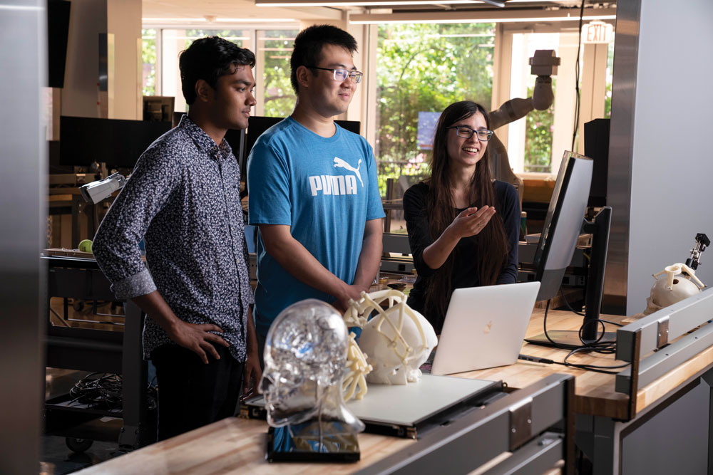
Graduate students Theodore Anyika and Chuchuan Hong (Graduate Students in ECE) worked with Prof. Justus C. Ndukaife to perform high-speed nanoscale optical trapping with a novel plasmonic double nanohole aperture device. (Anyika et al., 2023) Prof. Dan Fleetwood described interface traps, correlated mobility fluctuations, and low-frequency noise in metal–oxide–semiconductor transistors in Applied Physics Letters. (Fleetwood, 2023)
Dr. Bennett Landman has been selected as the next Editor-in-Chief of the SPIE Journal of Medical Imaging (effective January 1, 2024)! Congratulations!
Patrick Darmawi-Iskandar was selected as this year’s Founder’s Medalist for the School of Engineering. Darmawi-Iskandar studied electrical and computer engineering and was a SyBBURE Searle research fellow at the Institute for Space and Defense Electronics where he examined the effects of radiation on carbon nanotube field-effect transistors.
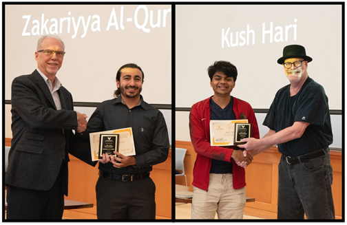
Zakariyya Samer Al-Quran earned the 2023 Program Award for Computer Engineering, and Kush Jayesh Hari earned the 2023 Program Award for Electrical Engineering.
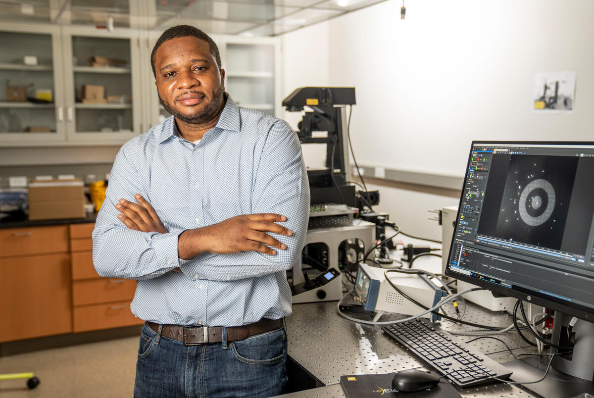
Prof. Justus Ndukaife was selected for an NSF CAREER award on “Resonant Dielectric Optical Metasurfaces for Single-Cell Extracellular Vesicles Analysis”.
Prof. Zhaohua Ding was elected to the American Institute for Medical and Biological Engineering’s College of Fellows.
Prof. Gabor Karsai was elected External Member of Hungarian Academy of Sciences
Prof. Bennett Landman was elected as a Fellow of the SPIE and earned the Chancellor’s Cup for Research Excellence.
Prof. Benoit Dawant earned the CTTC Master Innovator award.
Profs. Ted Bapty, Mona Ebrish, and Alan Peters were named IEEE Senior Members.
Prof. Enxia Zhang received the IEEE NPSS Women in Engineering leadership travel award.
Prof. Alan Peters was selected by his peers for the ECE Service Award.
Prof. Enxia Zhang was selected by her peers for the ECE Teaching Award.
Together students and faculty selected Cassandra Nunez as the Outstanding Teaching Assistant for 2022.
At ECE Day, we recognized Evelyn Marx for her best undergraduate poster, Aravind Krishnan with the runner up poster award, and Yubo Fan for the best poster award.
You can browse the 4222 manuscripts on Elsevier’s Scopus (April 2023) where our faculty collaborated with over 6,662 co-authors from around the world.
Bennett Landman, Chair
Tim Holman, Director of Undergraduate Studies
Alan Peters, Director of Graduate Studies
Jack Noble, Director of Graduate Recruiting
Department Administration Staff
Department of Electrical and Computer Engineering
Vanderbilt University
PMB 351824
2301 Vanderbilt Place
Nashville, TN 37235-1824